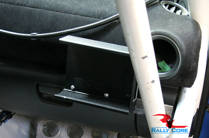
The computer should be mounted in such a way that the co-driver has access to the
computer when he is fully belted in. The mount should be made solid so that the
computer does not bounce while on stage.
To mount the computer, take the four #1
Philips screws out of the side of the computer that does not have the connector on it,
remove the side plate. Slide the front face plate out of the aluminum housing. Drill
holes in the back of the case that suit your mount and fasten with 8-32 screws with
washers and locking nuts on the back side.
When fastening, mind the fact that the
computer will have to slide back into the casing. Make sure that your fasteners are
not protruding into the case far enough to hit any of the delicate electronics, wires or
connectors.
The space available will be between 1 inch and ¼ inch depending upon
where the holes were drilled.
Do be careful not to touch the electronics inside of the
computer when the face plate is pulled from the casing, they are susceptible to
electrostatic shock.
The wiring harness should be laid out in the vehicle so that the harness approaches the rally computer from the top. From this point it can then be fed down to the floor of the vehicle where the power, sensors and intercom can go in separate directions.
The power should be routed to the easiest location to be able to pick up constant and switched power. (See Power Wiring section)
The sensors should usually be run to the ECU/ECM. (see Sensor Wiring section)
The intercom audio connections should be run along the co-drivers side of the car, either on the floor tied to the cage or along the ceiling, tied to the cage.
The audio harness should then run behind both codriver and driver, where the roll cage can be used to elevate the wiring harness to the desired entry point on the driver and co-driver's seats.
The co-driver's wiring harness is usually run along the restraint harness, and the drivers wiring harness often comes out on the drivers left shoulder hanging from the cage or simply run on the restraint harness in the same manner as the co-drivers.
The power wiring is comprised of five individual wires. There are two red, two black
and one white with red striping.
The red wires are to be wired to constant power or
battery.
The black is to be wired to ground or the chassis.
Finally, the white with red
wire should be wired to a switched power, usually a power supply that is switched with
the ignition key.
These power sources are usually easiest to find at the ECU/ECM, but
can always be found at the fuse box or at an OEM radio location.
Always wire both
ground wires and both constant power lines. There are two for redundancy and
reliability. The power supplied should be of a standard 12 Volt automotive power
system with negative chassis.
The wiring harness has two brown sensor wires. These are shielded two conductor
cables. The shield is already connected at the factory, and does not need to be
connected in the installation. The red and the black wire both need to be connected.
The red wire should be connected to whichever signal you wish to monitor, the black
should be connected to a ground located near where the sensor is tapped into. This
ground is often labeled “sensor ground” on an ECU/ECM. Any ground near where the
sensor will do, but the black wire must be connected.
Sensor wires should only be
connected to sensors that produce voltages that are less than 15 volts. Connecting
sensor wires to spark generators or ignition coils will damage the computer.
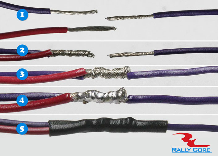
Most of the wiring will need to be spliced into existing wiring. Rally Core recommends
cutting the existing wire, stripping both ends of it back and physically twisting the new
sensor or power wire onto that wire.
The two ends should then be physically twisted
together and soldered.
Heat shrink should be used to create a new insulation over the
bare wire.
We do not recommend using ‘Vampire Taps’ or ‘Butt Splices’ as this can
lead to very unreliable connections. Please take the time to do wiring correctly; it will
pay off in the end.
 The computer should be mounted in such a way that the co-driver has access to the
computer when he is fully belted in. The mount should be made solid so that the
computer does not bounce while on stage.
The computer should be mounted in such a way that the co-driver has access to the
computer when he is fully belted in. The mount should be made solid so that the
computer does not bounce while on stage. 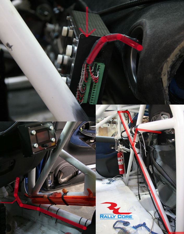 The wiring harness should be laid out in the vehicle so that the harness approaches the rally computer from the top. From this point it can then be fed down to the floor of the vehicle where the power, sensors and intercom can go in separate directions.
 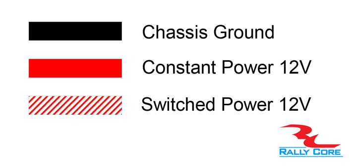 The power wiring is comprised of five individual wires. There are two red, two black
and one white with red striping.
The power wiring is comprised of five individual wires. There are two red, two black
and one white with red striping.  The wiring harness has two brown sensor wires. These are shielded two conductor
cables. The shield is already connected at the factory, and does not need to be
connected in the installation. The red and the black wire both need to be connected.
The wiring harness has two brown sensor wires. These are shielded two conductor
cables. The shield is already connected at the factory, and does not need to be
connected in the installation. The red and the black wire both need to be connected.
 Most of the wiring will need to be spliced into existing wiring. Rally Core recommends
cutting the existing wire, stripping both ends of it back and physically twisting the new
sensor or power wire onto that wire.
Most of the wiring will need to be spliced into existing wiring. Rally Core recommends
cutting the existing wire, stripping both ends of it back and physically twisting the new
sensor or power wire onto that wire.